The biggest misconception for 3D printing is that anyone can easily design parts and print them instantly. Even with recent advances in consumer-level 3D printing, 3D printing has yet to allow anyone to print parts without already having experience or spending the time to learn about the process. This guide breaks down the essentials on how to create designs for 3D printing if you are new to 3D printing or are struggling to achieve good results.
Know your technology
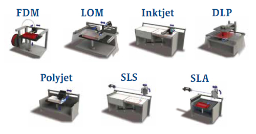
There are 7 main categories of 3D printing technology and each one is unique. There are different design guidelines for each. FDM uses spools of thermoplastic filament that gets heated in the hot end of the 3D printer and deposited in lines layer by layer. Since a majority of hobbyist printing uses FDM, I will focus on this type for this post.
Know your CAD and slicing software
Not all design softwares are the same, and there is usually separate “slicing” software needed to take your 3D model file and convert to to a g-code file that the machine understands. You should use whatever computer aided design (CAD) software you are most comfortable with when creating files to be 3D printed.
If you are new to CAD, we highly recommend Autodesk Fusion 360. The software is fully featured, fairly intuitive, and is free for hobbyists and students. Meshmixer is another good free tool from Autodesk to directly create, adjust, and repair stl files. Other free CAD options to check out include Blender, OpenSCAD, Google SketchUp, and TinkerCAD.
Materials to create designs for 3D printing
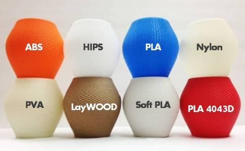
For FDM style printers, there is a limitation to materials that can be printed. Even with “metal” and “wood” filaments in recent years, all filaments are a majority thermoplastic based. PLA and ABS are the most common and PETG is growing in popularity. Exotic filaments based off of nylon and polycarbonate can be more difficult to print with and may not be compatible with your printer. It is important to consider the material requirements you need for your part when designing and selecting a material. ABS and polycarbonate have higher strength but are more likely to warp and print at higher temperatures. If you do not need the added strength, then choose PLA or PETG as they are much easier to print with. Also, PLA is biodegradable and PETG is recyclable.
Print surface and size
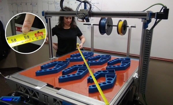
As you begin the design process, it is critical to make sure that your part can fit within the print dimensions of the printer you are using. Many hobbyist printers are on the scale of 200mm x 200mm x 200mm, making large parts impossible to print. One way around this is to split up a larger part into multiple smaller parts and adhere or fasten them together after you print.
With FDM printing, the print surface is critical to the fidelity of the print. Objects that have only round surfaces, such as a sphere, require extra support structure to be created to print the part. Keeping in mind which flat surface you would like your part to print on during the design process will make your part much easier to print.
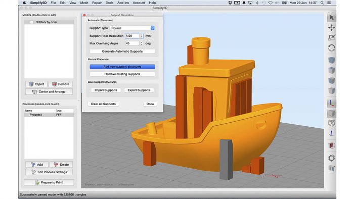
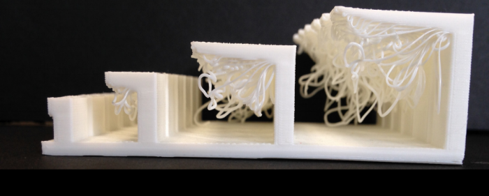
Overhang rule to minimize support
Once you know your prefered print surface on your part, your goal is to minimize support structures required. This is achieved by reducing.
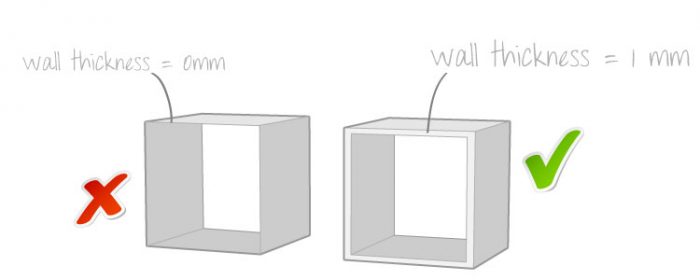
Minimum feature detail and wall thickness
As with any type of material and manufacturing method, the minimum feature detail and wall thickness must be considered. FDM 3D printers will generally print down to 1mm wall thickness without any issues. Lower than that will require testing. Any small features such as points, lines, holes, corners, and text are also subject to this rule. Features that are too small will become deformed or removed entirely, so consider feature size during the design process.
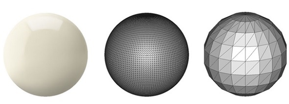
File resolution and units
When saving your files, be wary of your STL file save settings. Err on the side of caution and save your files with the highest resolution reasonably possible. This will help ensure smooth prints on curved surfaces. Alternatively, saving your files in very low resolutions can be used a fun design feature called low-poly, where the shape is printed in low-resolution triangles to give it a jagged look.
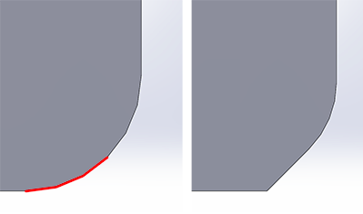
Chamfer up, radius sides
For nice surface finish and ease of printing, design your parts with chamfers up from the build surface, and fillets as viewed from above. This concept relates back to the overhang rule with FDM 3D printing. Radius edges from the build surface break the rule while 45 degree chamfers do not. Fillets can be used in any other areas of a part except for print surfaces and overhangs.
Holes are prefered printed vertically
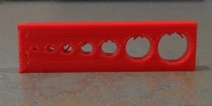
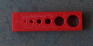
Vertically printed holes develop very well in parts. However, horizontal holes will suffer from the overhang rule and will become slightly or highly deformed. Large holes generally require support structure while smaller holes can be printed without issue.
Teardropping or support structure is recommended for holes larger than 10mm. Unless adjusted for in the print settings or in the design, horizontal holes tend to turn out slightly oval shaped with the horizontal dimension oversized and the vertical dimension undersized.
Threaded holes
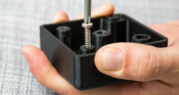
There are 3 main methods to do threaded holes in 3D printed parts. The first is to design threads into the part and print the threads. This only works if the threads are large enough as it relates to the minimum feature size discussed above. The second method is to print a straight hole and then tap the hole after the part is finished. This requires having a tapping tool and the patience to use it for every hole that needs to be threaded. The third method consists of self tapping the holes with the fastener used. Self-tapping or thread forming screws for plastic are designed for this and perform very well. Other options include wood screws and machine screws, but require tighter tolerances of the printed parts.
Free part complexity
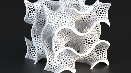
One of the best characteristics of 3D printing is that part complexity is essentially free. Added cuts, patterns, or intricate details in traditional manufacturing methods would quickly increase the part or mold cost. 3D printers are mostly concerned with the amount of material used, so feel free to design complexity and patterns into any parts. Unlike other technologies, 3D printing permits parts located within parts and assemblies printed together at once, opening up the design space to some unique and innovative creations.
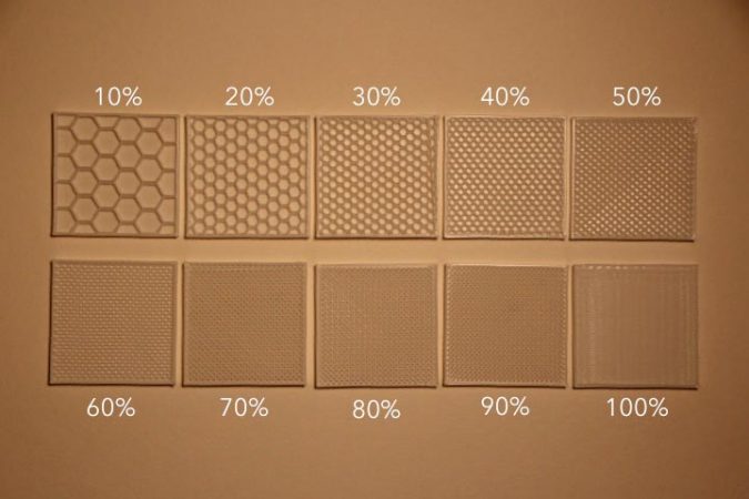
Free infill complexity and percentage
In slicing software, there is the option to change infill types and percentage. One major benefit to 3D printing is that parts do not have to be 100% filled with material. This allows you to save on material costs and print time when you need. 20% infill is very common for parts and it gives you roughly 50% of the strength compared to 100% infill. Save on plastic usage by reducing infill and outer wall layers in your parts.
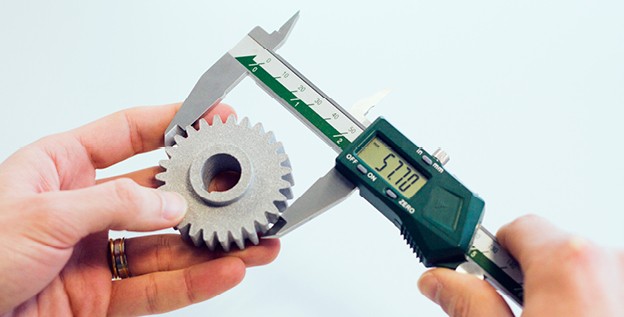
Tolerances
Tolerances will vary depending on your 3D printer. FDM printers will range from +/- 0.1mm to 1mm tolerance. For general use printers, the tolerance should be +/- 0.5mm, while professional printers can get to +/- 0.1mm. It is important to note that there is surface texture from the layer depositing process in the direction of the Z-axis of the printed part. If this is unacceptable, there are post processing techniques such as sanding, acetone vapor smoothing, and filler primer painting that can be used to smooth the parts.
You might also be interested in these 3D printing blogs: